ID.4 2021 ➤, ID.3 2020 ➤
Electric rear-wheel drive EIP220 and all-wheel drive EIA200, EIP220 - Edition 11.2021
12
Charging socket
12.1
Assembly overview – charging socket
1 - Bracket
2 - Bolt
❑ Qty. 2
❑ M6 x 20
❑ 8 Nm
3 - High-voltage battery
charging socket 1 -UX4-
❑ With charging cable
❑ ⇒ Rep. gr. 93; Remov‐
ing and installing high-
voltage battery charg‐
ing socket 1 [UX4]
4 - Bracket
5 - Bolt
❑ Qty. 4
❑ M6 x 18
❑ 8 Nm
6 - Bolt
❑ Qty. 4
❑ 8 Nm
7 - Charging flap unit
❑ ⇒ General body re‐
pairs, exterior; Rep.
gr. 55; Charging flap
unit; Removing and in‐
stalling charging flap
unit
8 - Charging cable
❑ With high-voltage bat‐
tery charging socket 1
-UX4-
12.2
Removing and installing high-voltage
battery charging socket 1 [UX4]
The high-voltage battery charging socket 1 -UX4- will hence‐
forth be referred to as “charging socket”.
Removing
DANGER
High voltage can cause fatal injury.
Danger of severe or fatal injuries from electric shock or elec‐
tric arcs.
– Have a high-voltage technician (HVT) or a high-voltage
expert (HVE) de-energise the high-voltage system.
250
Rep. gr.93 - Electric drive systems

ID.4 2021 ➤, ID.3 2020 ➤
Electric rear-wheel drive EIP220 and all-wheel drive EIA200, EIP220 - Edition 11.2021
– ⇒ Rep. gr. 93; De-energising high-voltage system.
Note
The charging socket can only be removed in conjunction with
the charging cable.
– Open luggage compartment right side trim
– Detach manual release mechanism -2-.
– Disconnect electrical connector -3-.
– Release cable duct -1-.
– Remove charging flap unit ⇒ General body repairs, exteri‐
or; Rep. gr. 55; Charging flap unit; Removing and installing
charging flap unit.
– Remove rear right wheel housing liner ⇒ General body re‐
pairs, exterior; Rep. gr. 66; Wheel housing liner; Removing
and installing rear wheel housing liner.
High-voltage battery, 55 and 62 kWh
– Remove rear centre underbody cladding ⇒ General body re‐
pairs, exterior; Rep. gr. 66; Underbody cladding; Removing
and installing rear centre underbody cladding.
– Remove reinforcement for high-voltage battery body aper‐
ture ⇒ Rep. gr. 93; Assembly overview – high-voltage bat‐
tery, installed, 48, 55, 62 kWh
All vehicles (continued)
– Lower rear axle in front area ⇒ Running gear, axles, steer‐
ing; Rep. gr. 42; Rear axle; Lowering rear axle.
– Disconnect connector -1- on charging unit 1 for high-voltage
battery -AX4-.
– Separate connector -2- on high-voltage battery 1 -AX2-.
– Remove hose -1-.
12. Charging socket
251

ID.4 2021 ➤, ID.3 2020 ➤
Electric rear-wheel drive EIP220 and all-wheel drive EIA200, EIP220 - Edition 11.2021
– Unscrew bolts -2-.
– Unscrew bolt -3-.
– Unscrew bolt -4-.
– Release wiring fasteners -5-.
– Remove charging socket with bracket.
– Detach Bowden cable for manual release mechanism -1-.
– Remove electrical wire -3- from guide.
– Unscrew bolts -2-.
– Detach charging socket from bracket.
Installing
Install in reverse order of removal, observing the following:
WARNING
High voltage can cause fatal injury.
Danger of severe or fatal injuries from electric shock or elec‐
tric arcs.
– Have a high-voltage technician (HVT) or a high-voltage
expert (HVE) re-energise the high-voltage system.
– ⇒ Rep. gr. 93; Re-energise high-voltage system.
252
Rep. gr.93 - Electric drive systems

ID.4 2021 ➤, ID.3 2020 ➤
Electric rear-wheel drive EIP220 and all-wheel drive EIA200, EIP220 - Edition 11.2021
Tightening torques
♦ ⇒ Rep. gr. 93; Assembly overview – charging socket
12.3
Removing and installing actuator for
high-voltage charging socket lock 1
F498
Actuator for high-voltage charging socket lock 1 -F498- is refer‐
red to as actuator below.
Removing
DANGER
High voltage can cause fatal injury.
Danger of severe or fatal injuries from electric shock or elec‐
tric arcs.
– Have a high-voltage technician (HVT) or a high-voltage
expert (HVE) de-energise the high-voltage system.
– ⇒ Rep. gr. 93; De-energising high-voltage system.
– Remove charging flap unit ⇒ General body repairs, exteri‐
or; Rep. gr. 55; Charging flap unit; Removing and installing
charging flap unit.
Note
It is only necessary to release charging socket; lowering rear
axle is not required.
– Detach charging socket ⇒ Rep. gr. 93; Removing and instal‐
ling high-voltage battery charging socket 1 [UX4].
– Disengage Bowden cable for manual release -1-.
– Remove bolts -3-.
– Remove actuator -2-.
Installing
Installation is carried out in reverse order; note the following:
– When installing, ensure that actuator makes contact with
contact surface correctly and that bolt mountings are not
damaged.
– Connect and disconnect electrical wiring according to spec‐
ifications for repairing wiring harnesses and connectors
⇒ Electrical system; Rep. gr. 97; Connectors; Repairing
electrical wiring harnesses and electrical connectors.
12. Charging socket
253
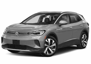 2024 VW ID.4 Owner's Manual